

We are developing the following application platforms:-
- RFID based Sensor network.
- Sensor based modules with controller.
- Zigbee based sensor Adhoc network.
- Intelligent Master Control Unit.
- Wireless Power transmission system.
A) RFID based sensor network
Unit Functions:-
- RFID reader can able to read 20 to 30 RFID tag at a time with anti-collision features.
- Active RFID Tag, RFID reader is Yellow Beam’s own design.
- RFID reader has a tunable antenna feature.
B) Sensor based Modules
The following sensors modules are used in the sensor nodes. Some of the modules are placed in the on board and some of the other modules are placed in the measurement point (field) itself. It is depends upon the application. The following sensor modules are used in the measurement process
1. Ultrasonic Sensor
2. IR-Distance measurement temperature
3. CH4, CO, H2S, CO2, LPG Sensors.
4. Axis accelerometer, tilt-sensor, vibration, proximity
5. Compass sensor.
6. PIR sensor
7. Colors sensor
8. Object sensor
9. Humidity sensor
10. Flex sensor & Hall Effect sensor
11. IP Camera.
12. GPS module
C) Zigbee based Adhoc network
Block diagram of the Portable Terminal II:-
Block Diagram of the PT – II Adhoc Network:-
Unit Functions:-
- Portable Terminal-II contains sensors and communication networks. so it will communicate with each other and Host unit also.
- These units are forms a Adhoc networks.
- This unit has GPRS function so that it transfer the field data to external world through GSM network.
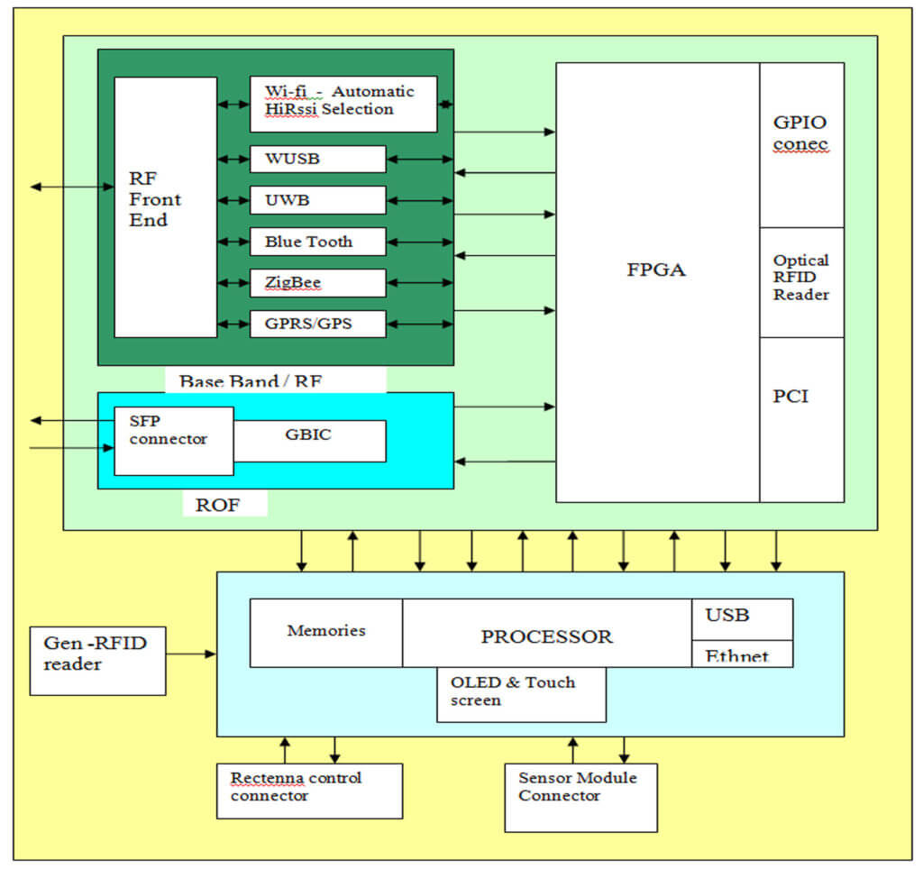
D) Intelligent Master Control Unit:
Block Diagram of the Unit:-
The above Master unit having the following communication networks,
High speed communications,
- Wi –Fi
- UWB
- WUSB
- Bluetooth
- ROF
- Ethernet
Low speed communications,
- GPRS/GPS
- Zigbee.
Unit Functions:-
- This unit can act as PT-I and PT-II.
- This unit has Radio over fiber interface. So that optical information converts to any one of the high speed communication network.
- This unit can act as a MicroRBS in ROF communication. It covers small area.
- High speed video streaming is possible to monitor the field.
- Measured sensors parameters are transferred to any one of the communication network.
- It is having UWB supports so that we can develop our own accurate position monitoring system in centimeter basics.
- The Master unit can communicate to another master unit through any one of the network..
- The network selection process depends upon the environmental condition. The network selection automatically done by the master unit.
- Adhoc network also possible between the master units.
- This unit has only one RF Antenna for all communications.
- All wireless communications “Applications” are run in the Processor.
E) Wireless Power Transmission System:
All above units are powered remotely, so each unit has the rectenna. The power is transmitted through the separate microwave communication network. The rectenna contains the array of fractal shaped antenna. Fractal has mutifrquency response and size also small compared with normal patch antenna.
Rectenna Block diagram:-
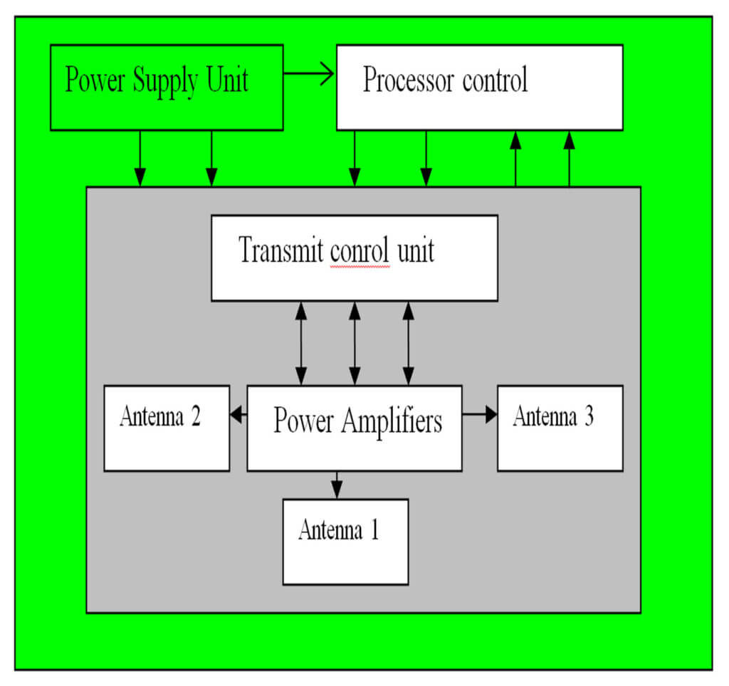
Transmitter Block diagram:-
Transmitter has the processor and high power RF energy transmitted unit. This energy is transmitted through three horn antennas. Each placed three directions so that it covers the full area.


