
Intelligent RFID based cable management/patch panel mapping:-
What’s the problem and the solution we will be focusing on ?
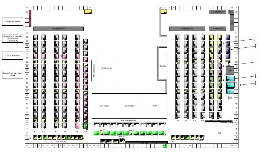
Current setup
Focus is on the maintenance and updating of the above harness setup ?? what Other competitors cant offer ?
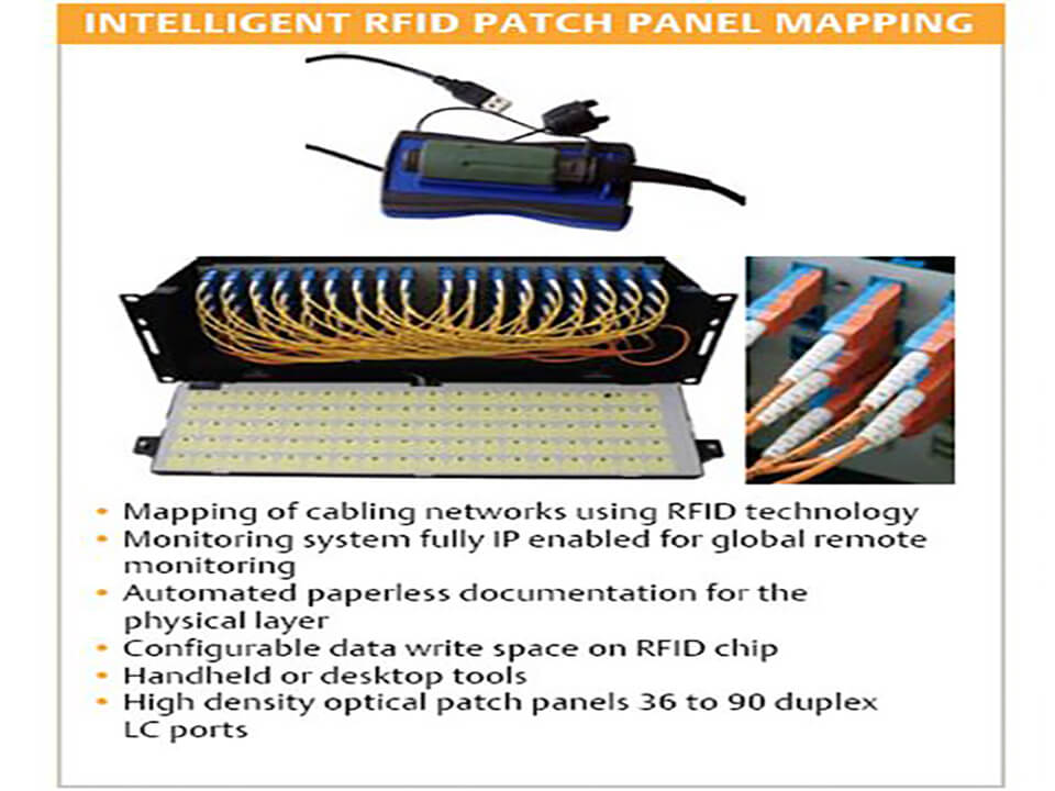
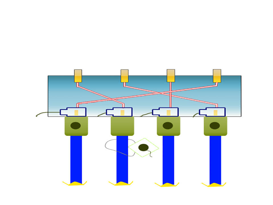
High density optical fiber patch panels ranging from 36 to 90 port duplex LC adapters on distribution panels .RFID monitoring system fully IP enabled and can be addressed real-time from across the world Flexibility in physical layer management and automated paper less documentation Local or remote live management of installation and post-installation change control and network security .Additional customer configurable extra data write space on RFID chip . Monitor and locationlize the following types of cabling like structured, fiber, coaxial, riser , electrical .
Tested it on the RJ45 CAT5;RJ-11 cabling, co-axial cabling, fiber cabling.
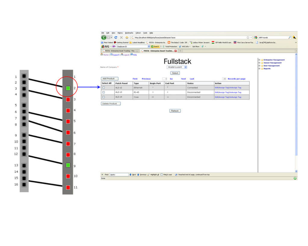
It shows where and all the ofc has been plugged and unplugged and where it has been traversed ofc history log layout details .
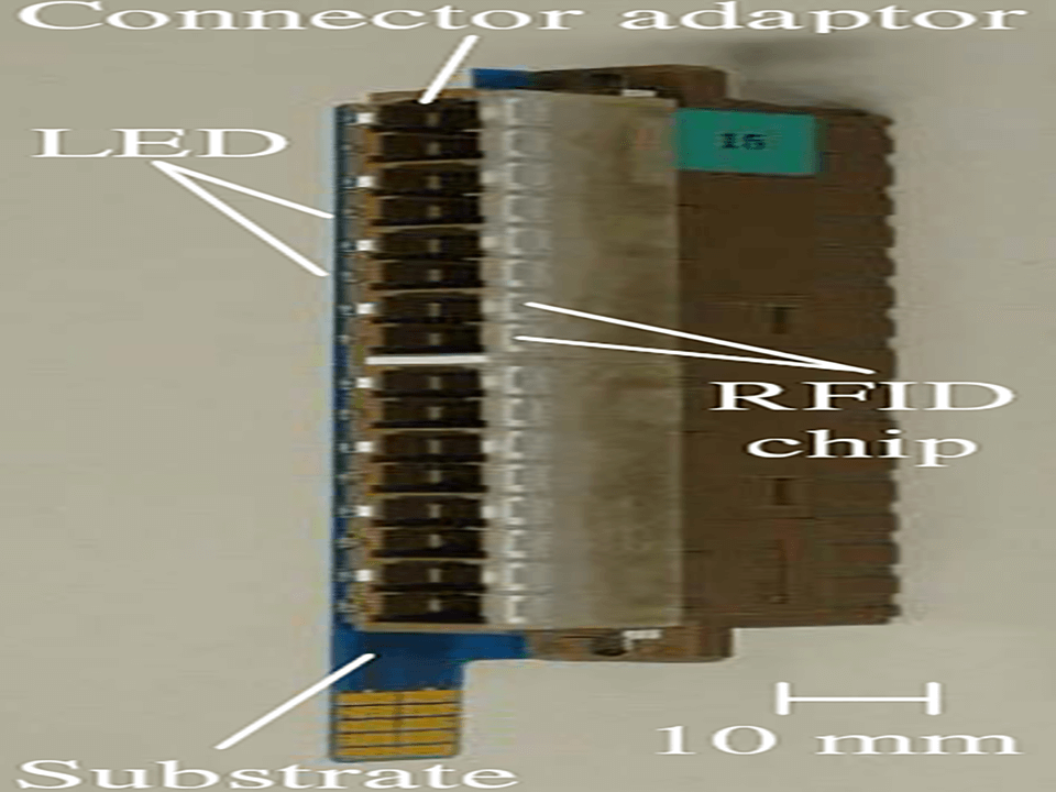
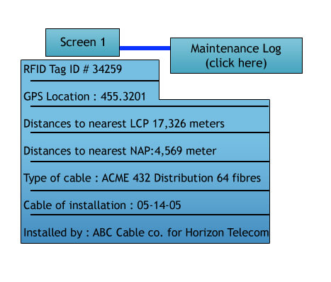
other parameters like the temperature , pressure ,crossing the bend radius , fiber break are all will be shown , currently achieved the first three via the sensor log intimation , below shown are the Screen shots of the RFID experimental cable management setup .
The performance data then resides with the transponder for the product lifetime and can be retrieved by the RFID enabled patch panel system or CR RFID reader. Data envisioned for this feature could include validated test data of performance parameters, such as insertion loss, back reflection and end-face geometry, as well as product traceability information, such as measurement date, operator, and test station identification.
UHF operating frequencies allow low-power and long-range communication for efficient operation. Its outstanding anti-collision multi-tag-handling algorithm provides clear communication to a large number of tags for tracking of assets or people.
Yet to test it on the power and control cabling(AC/DC) , from the experimentation I derived that SAW tags when used for the electrical power cabling better results are observed, these will be revealed in detail in the FIT form .
The FE SW I am planning to develop will showcase the below mentioned features
The change control state machines powered by RFID reader assists in automating and manages the process. So through this SW control users can always be aware of changes occurring in their infrastructure and the manner in which those changes affect the physical layer. The contents of the RFID database (which is ODBC [Open Data Base Connectivity]-compliant and features an API [application program interface] and SDK [software development kit] for integrating with the application which is under design phase can be associated with the application interface which the physical location of the assets stored in the database.
Other feature planning to include automatic network snapshots generation and send them automatically to requesters (use email), display of equipment in two dimensions .
Apart from this I have thought of and started incorporating the following in the application FE
Maintain permanent records of physical location and connections for every circuit Record the equipment, cables, and pathways for the cable plant .Define the connectivity and circuit routes .Identify space capacity while planning major moves and changes .Service Request and Trouble Ticket management(Specific to BU mostly managed by the lab at tenders/Managers) .Store information for multiple buildings or campuses and show views by floor, closet and zone. Disaster Recovery Records.
FIT invention submission form will cover how we can make the system to automatically provide complete link information in a graphical format, providing full end-to-end visibility, automatically updating in real time as changes occur , Continual monitoring for illegal connections, disconnections or tampering for increased network security.
Apart from this I wanted to showcase the following while handling the OFC , trough custom designed optenna based rfid ability to measure the propagation loss inside the fiber , calculation of twist-induced strain spots , Minimum Bend Radius , Fiber Cable Loaded Minimum Bend Radius , Fiber Cable Unloaded Minimum Bend Radius , Pulling Tension , ZIF shear spots
What’s been achieved till now ?
Will be testing it on the 32-bit embedded FPGA web server with a star , ring configuration shortly and the details of the same will be covered in a separate FIT
Proposal for a RFID-based Tracking Solution OFC Cable Management
Project Objectives
The objectives for this project are:
1. Uniquely identify each cable end.
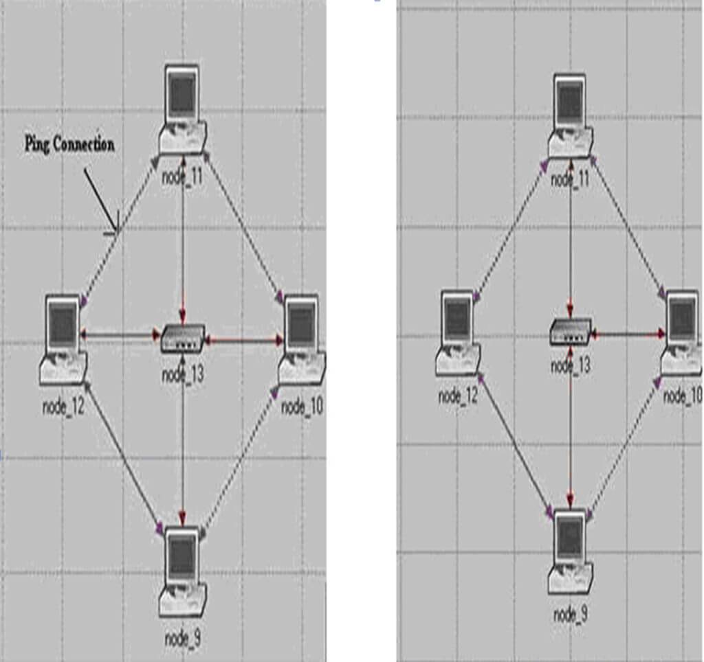
2. Identify the network topology for different test conditions
3. Identify cables that are not connected to the Patch Panels or Switch in an automated manner thereby reducing the manual effort and time delays involved in such tracking
RFID-based tracking solutions
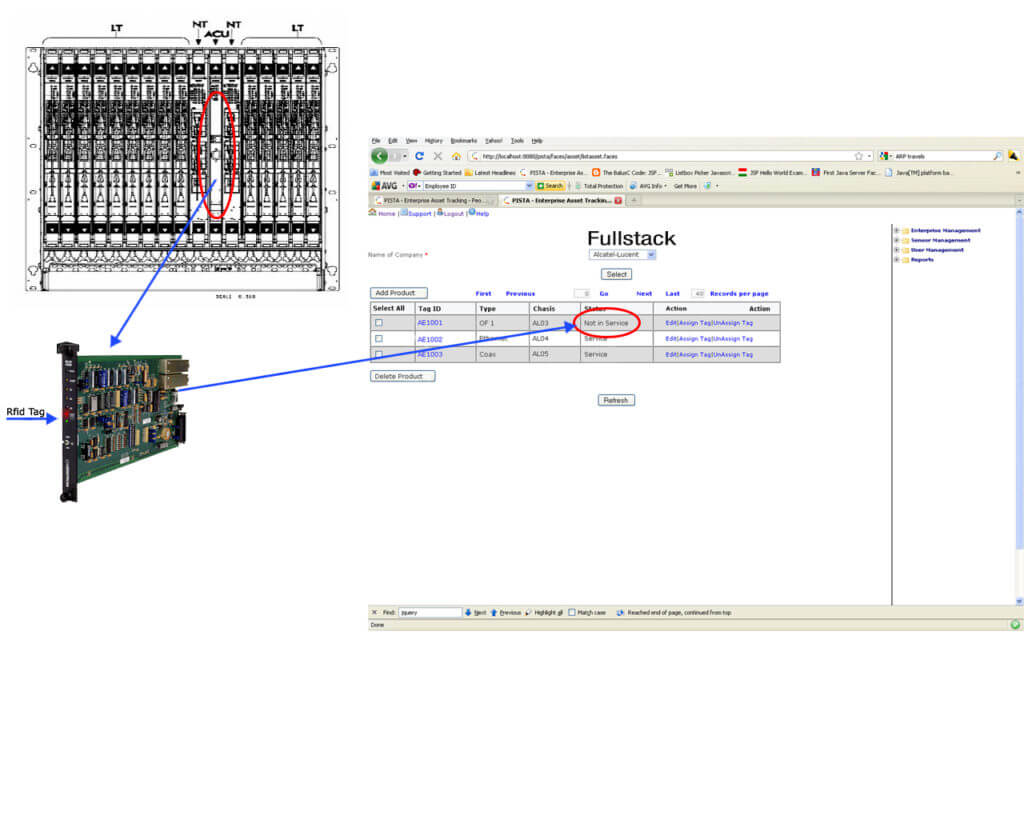
RFID is one of the widely-used technologies for automatic tracking of items, people and vehicles. Ennovasys uses a unique combination of RFID and GPS to track the position of assets whether it is inside or outside the organization. For this purpose, Ennovasys has built fullstack – an enterprise-level location management software with all the necessary tools to provide enterprise-wide visibility. Ennovasys plans to build the Network Diagnostics application on top of fullstack.
Technology Proposed
Ennovasys can provide the following components for this project:
- Semi-passive tags and/or Sensors
- Antennas/Readers
- Fullstack Software with necessary connectors
- OFC Cable Management Software
- Installation Support
- Passive and Sensor Tags
A passive tag is an RFID tag that does not contain a battery; the power is supplied by the reader. When radio waves from the reader are encountered by a passive RFID tag, the coiled antenna within the tag forms a magnetic field. The tag draws power from it, energizing the circuits in the tag. The tag then sends the information encoded in the tag’s memory.Passive, UHF technology based on the EPC Gen 2 protocol is being used to track the cables.
b) Antennas and Readers
A device used to communicate with RFID tags. The reader has one or more antennas, which emit radio waves and receive signals back from the tag. The reader is also sometimes called an interrogator because it “interrogates” the tag.
The readers feature 860-960 MHz regulation, maximum working range 4-7m with each antenna, configuration software with various options for each of 4/8 antennas and scan delay and anti-collision support.
RFID UHF External Antenna is a general circular polarised patch type and can be used with all type of UHF RFID reader available in the market. The frequency band (860-960 MHz) provides flexibility of selection to the customers.
The antenna features 8±0.5 dBi, impedance of 50 Ohms, horizontal/vertical tilt +90° to -90°, fixed metallic clamp, and various mounting facilities.
RFID 8-Port Reader (RIFI-8P)
The RIFI-8P is the out come of uphill struggle and market research of IAITO Team to meet the industrial proficiency and cost competency with the present market stipulate.
The goal of designing RIFI-8P is to provide a complimentary platform for the users to experience the expediency of extensive long range area exposure of RFID applications.
The RIFI-8P surmounts the hurdles of lower cost competency, performance accuracy, deployment flexibility, environmental adaptability, regulation compatibility and stimulation in application with incorporation of SDK, for the customers who wants to reinforce new era in RFID applications.
Some Key Features & Benefits
High sensitivity
Enterprise-class management and monitoring
Frequency Supported:865-867 MHz, 869 MHz, 915 MHz,
950 MHz.
Reads multiple tags with a single scan
Max. working range 7m (ideal conditions)
Software control flexibility
Field-upgrade capability
A Glimpse on RIFI-8P
AIR-Interface Protocols EPC C1G1/ C1G2 and ISO 18000-6B/6C
Tag Supported Alien, STMicro, Fujitsu, NXP, Rafsec, Atmel, Avery Dennison, TI, Hitachi, Impinj, Omron, Caen RFID
Frequency 865-867 MHz, 869 MHz, 915 MHz, 950 MHz
Working Range Ideal range: 4.2m to 7.1m (Ideal Conditions)
Anti Collision Performance Supported
Software Support LAN & RS 232 (Available) / USB (Customization)
Host Interface Connectivity UHF Reader Console 2.0 (SDK available)
Antenna Port 8 SMA Ports (Software Selectable)
Regulation Supported ETSI, FCC, India (TRAI)
c) Location Engine Software
Fullstack is built on J2EE with the capability to connect to various passive RFID readers from leading providers like Alien, IAITO, Motorola and Impinj. Fullstack provides low total cost of ownership TCO), as it is built on open source components.
Supported Platforms
Windows XP
Windows 2003
Linux
Supported Databases
Postgres and other JDBC-compliant databases
J2EE Server
JBOSS 4.x and other J2EE servers
Standards
EPCglobal including EPC-IS
Protocols Supported
TCP, JMS, RMI, HTTP, BPEL, WSDL, JDBC, File
d) OFC Cable Management Software
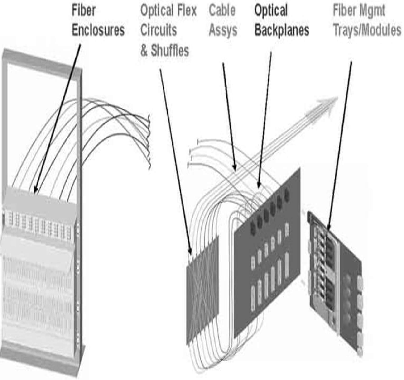
1. Current Manual Fibre Management
Monitoring Optical Networks
• Optical networks must be monitored for performance and security
– QoS at handoff: backbone networks, transoceanic landing sites, carrier interconnects, PoP, and demarcation points within a network
– CALEA requirements, IP assurance, Intrusion detection
Today this is done manually
Manual Fibre Monitoring
• Passive fibre tapping currently uses low-density, bulky, and expensive tap splitter modules
• Optical power monitoring requires individual detectors on all ports, adding cost and complexity to the Central Office or Landing Station monitoring location
• Optical performance monitoring requires optical selector switch to share expensive test equipment
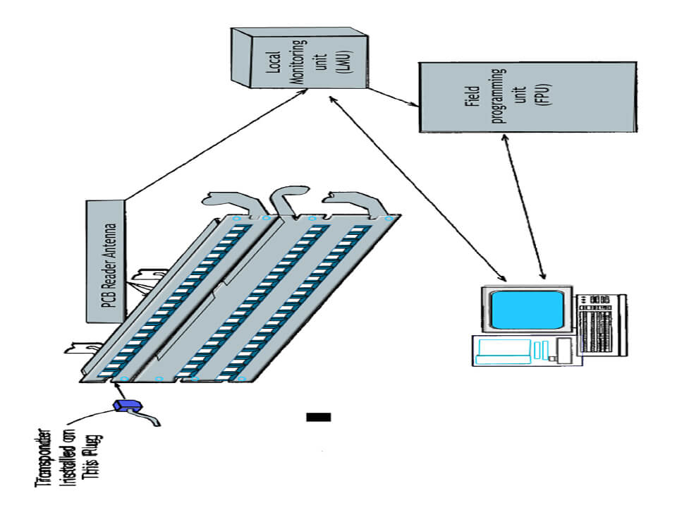
Steps involved to implement the OFC Cable Management Solution
• Passive or Sensor tags are attached at the ends of the cable.
• The RFID/Sensor reader is capable of reading all the tags and uniquely identifying the location of each tag.
• Readers are attached near each patch panel and switch to uniquely identify the location of each read point.
• Tag/Sensor information will be collected at different locations and passed on to the fullstack Software.
• Fullstack, which will be running at a central location, has reporting modules, reader management, SMS/Email based alerts, configuration module and connectivity to ERP systems like Quality Management System. Fullstack can be accessed by anyone in the network through a browser.
• Database (MySQL) and application server (JBoss) are usually bundled with Fullstack on delivery. If there is a need to use any other database, we can take a look and migrate it.
• Customized logics and screens will be built to input the information of each cable, its end tags and associate them with a network topology.
By attaching a RFID tag to each cable end, we are able to uniquely identify each end-point. Stored in the memory of each tag is a shared number that uniquely identifies the two tags as belonging to one cable.
The junction panels are replaced with low cost RFID readers capable of reporting the location of each tagged cable end. The technique offers several desirable features:
• Each cable end is uniquely identifiable.
• Tracking can be automated and is done in real-time.
• The solution is contact-less. During reading, the cables and connections remain undisturbed.
• Tags can be applied to industry standard cables.
• The technique is easily adapted to the existing cable infrastructure.
• No exposed contacts or connectors on cables, patch panels or probes.
• Universal reader concept comes with the ability to read both photonic and passive tags.
• Good sensitivity between reader to tags embedded in the cables for both copper & optics.
• Incorporates robust tag to tag inter-communication and anti-collision algorithms.
• Multiple readers are connected to the Fullstack software, the data is filtered and organized in a database
• Reader can read close to a thousand tags per second. To make sure all tags are read we keep the reader open for a period of time 60-90 seconds collect all the tags and then filter them.


