
Our ATM project contains the following 4 Modules:
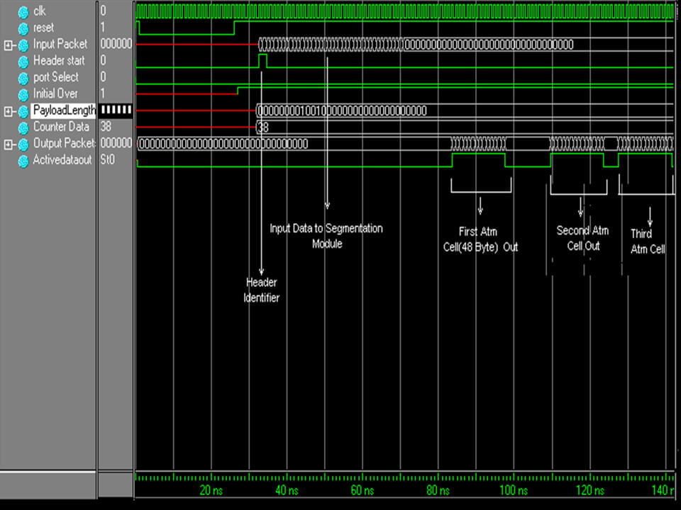
Segmentation Module
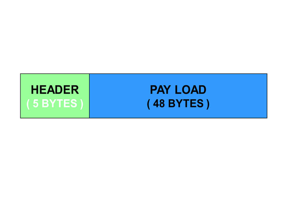
Here the incoming packets (packet size = 144 bytes) is split into
- ATM cell payloads
- ATM payload size = 48 bytes.
Host Interface Module
Here the header information is attached to the payloads.
Header information = 8 bytes (5 bytes + 3 bytes)
Payload size = 48 bytes
Cell size = 56 bytes
It is quite normal for the following question to arise at this juncture
How is it that the cell size is 56 bytes instead of 53 bytes?
The answer is that!!!
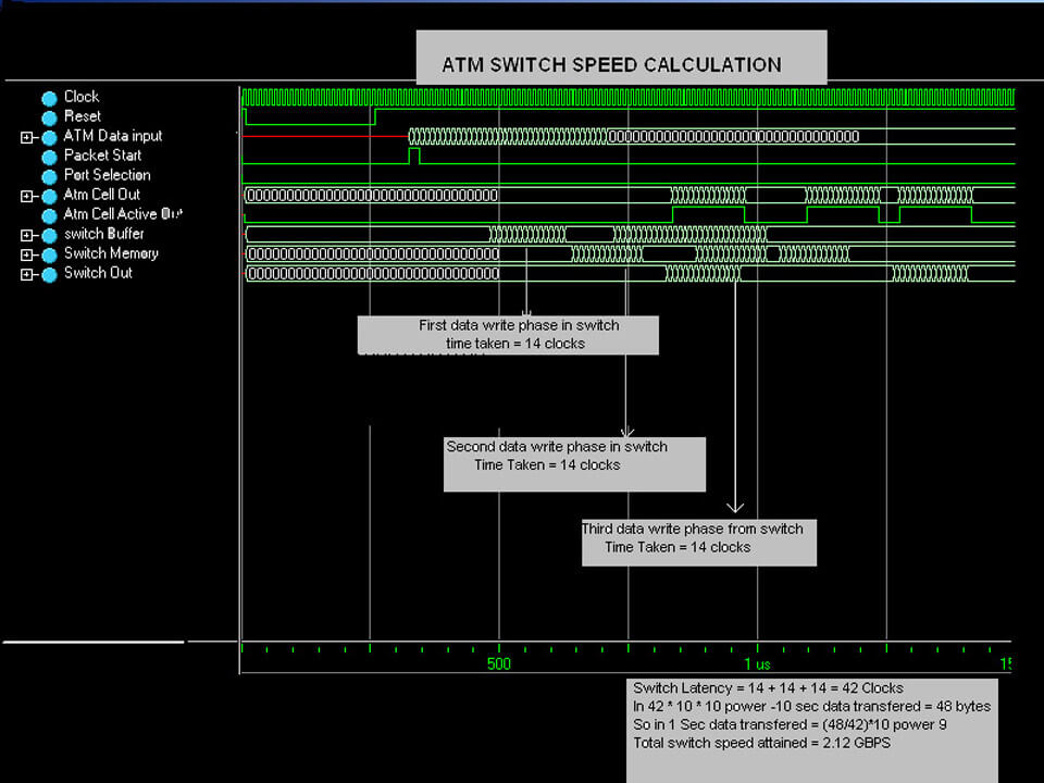
The odd size ATM cell doesn’t map easily into the common 32- and 64-bit-wide architectures of most processor today. Thus, within the Fore Runner switch, a 53-byte ATM cell is handled internally as 14 consecutive 32-bit words. Two additional fields round out the difference (since 14*4 = 56). The extra 3 bytes are divided into PAD 1 of 8 bits and PAD 2 of 16 bits
Cells move around the switch in this format, which has the advantage of being the multiple of 32 bits and adding some functions for error control. The PAD 1 byte is a CRC check on the first 5 header bytes. It provides further error control on the header exclusive of the HEC. The PAD 2 field is used by the control port to check for various errors in the ATM cells.
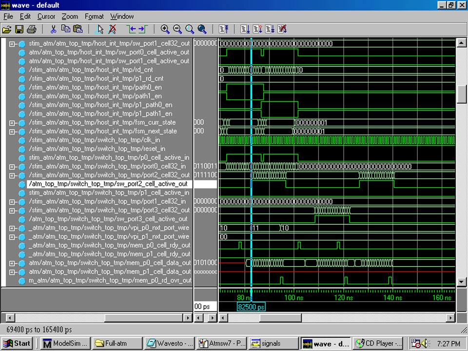
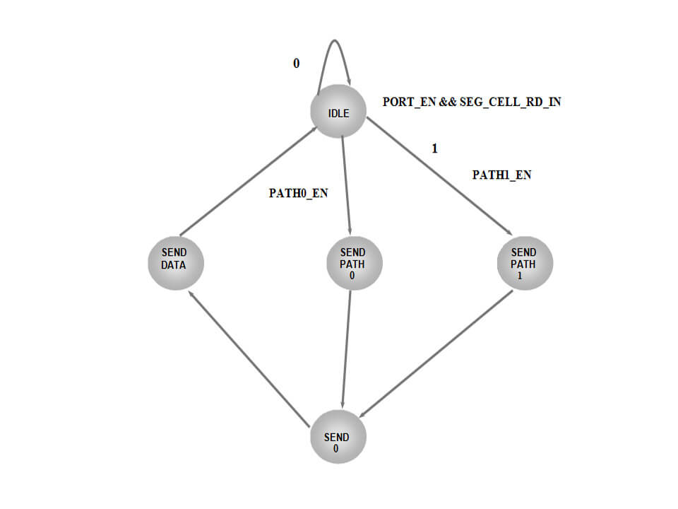
The above FSM (Finite State Machine) explains the operations inside the Host Interface Module.
The port is selected in the stimulus module. From the idle state the transfer takes place to either send path 0 or send path 1 state depending upon the path enabled(initially the path 0 is enabled; paths are enabled alternatively. In send path state the first 4bytes of header containing the VPI address is sent to the port cell32 out line to Switching Module and transfers to the send 0 state. In the send 0 state the remaining 4bytes are sent to the port-cell32-out line and it transfers to the send data state. In send data state the payload from segmentation module is send to the port cell32 out line to Switching Module.
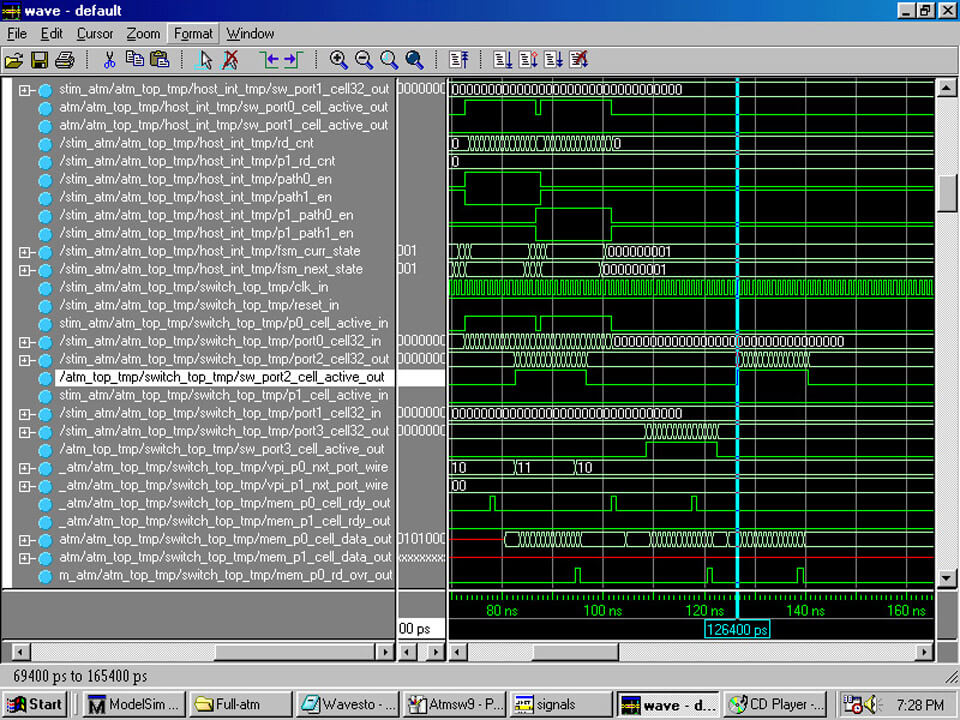
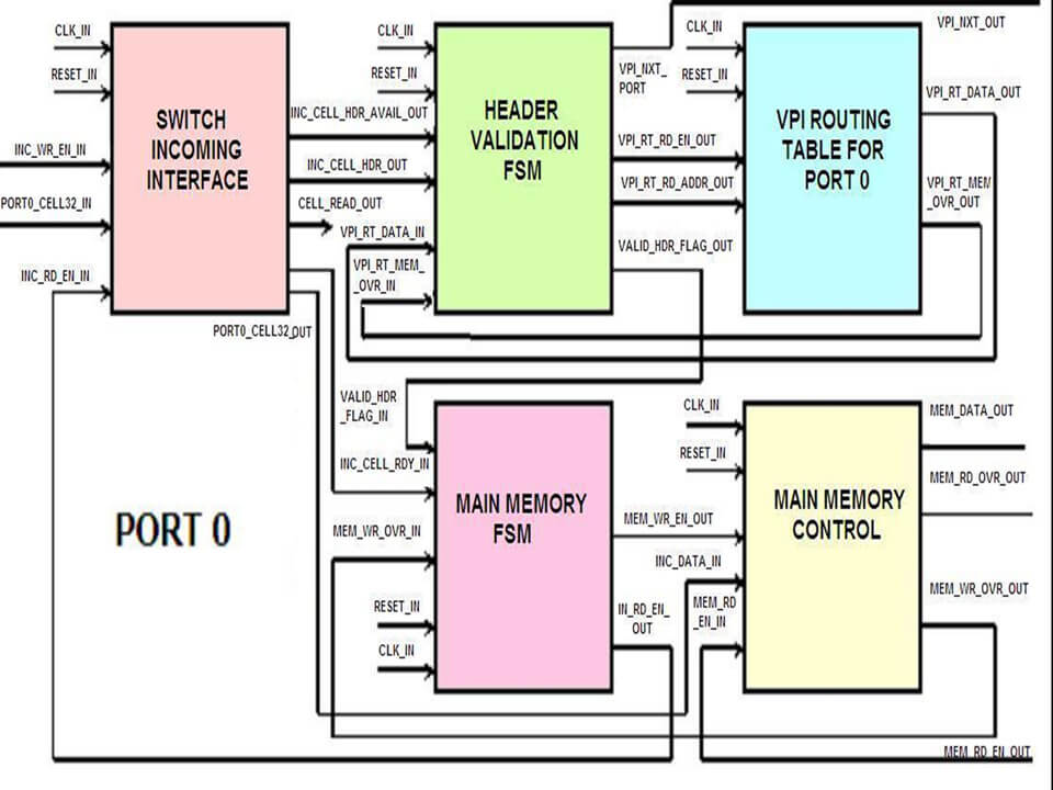
Switching Module
The switching module consists of the following submodules
- Switch Incoming Interface (SII)
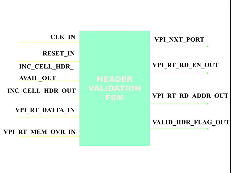
- Header Validation FSM (HVF)
- VPI Routing table (VRT)
- Main memory FSM (MMF)
- Main Memory Control (MMC)
- Main Switch FSM (MSF)
- VPI Translation Table (VTT)
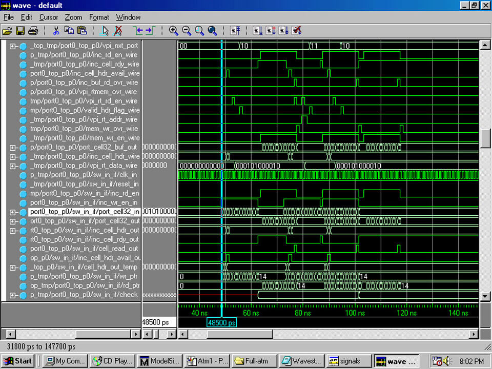
When cell-active-in flag is set by the host interface module, cell information is sent via the cell32-in line in terms of 32 bits at a time. (1 span =32 bits; 14 spans = 1 ATM cell). This information is stored in SII’s internal buffer.
The header is extracted by SII and sent to the HVF via inc-cell-hdr-out line after setting the inc-cell-hdr-avail-out flag.
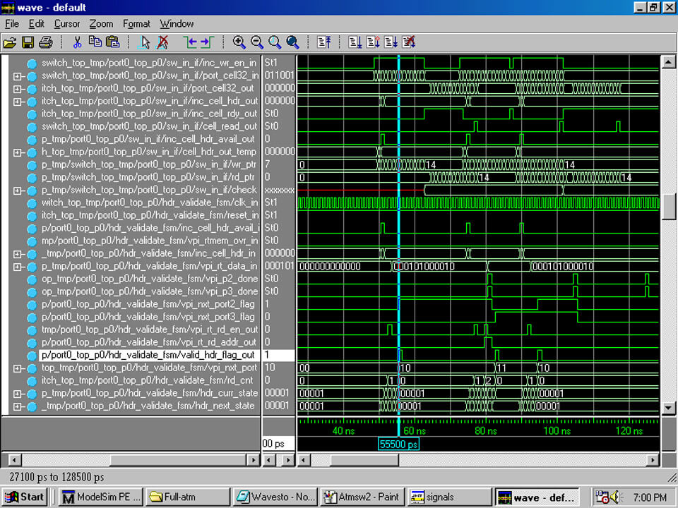
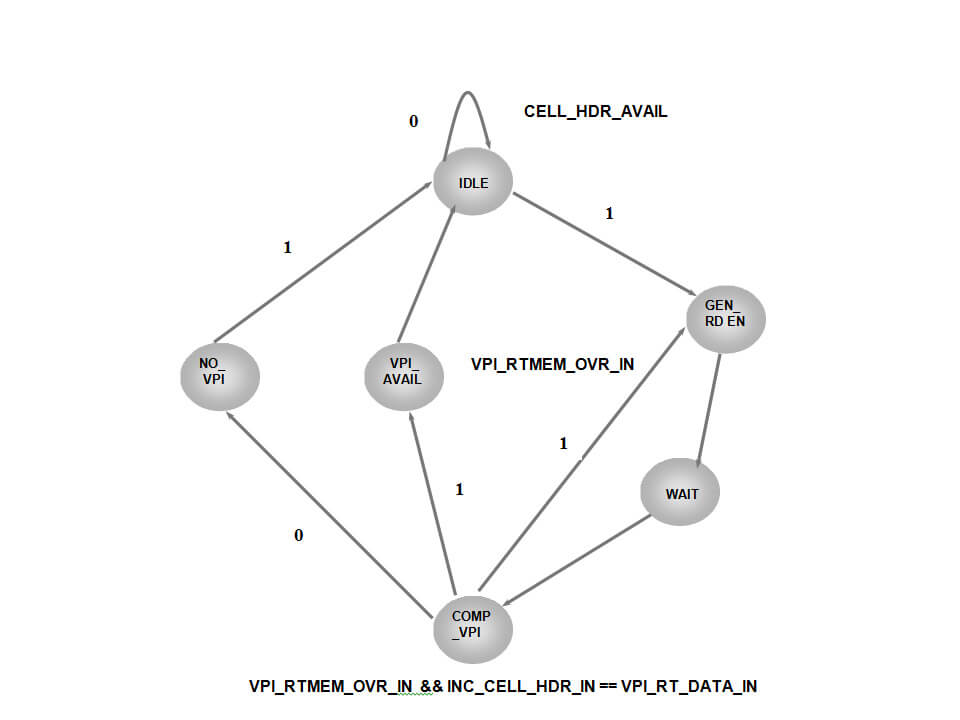
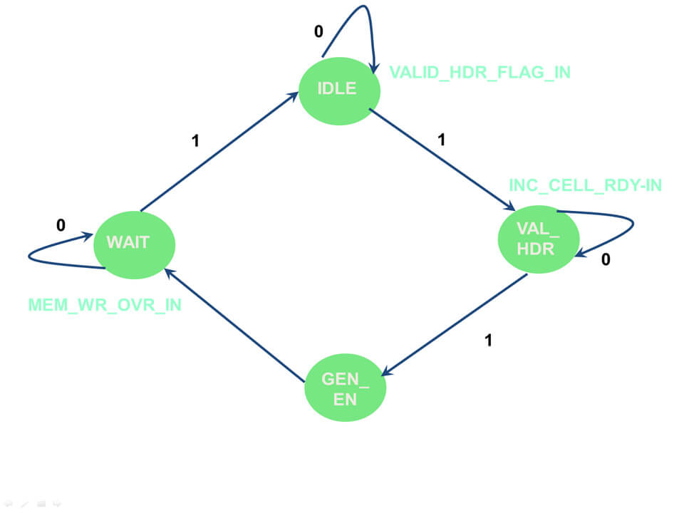
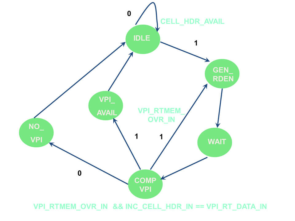
The above FSM (Finite State Machine) explains the operations inside the HVF.
When the inc-cell-hdr-avail-out flag is set, transfer from idle state to gen-rden state occurs. In gen-rden state , the address is sent via vpi-rt-rd-addr-out line to the VRT to fetch the VPI (This VPI information is already stored in the routing table). This VPI is compared with header VPI in the comp-vpi state. If they match, transfer to vpi-avail state takes place, where the valid-hdr-flag-in is set for MMF. If not, transfer to gen-rden state takes place , where fetching of the next VPI stored in the VRT takes place and the process is repeated. If no matching occurs, the cell is discarded.
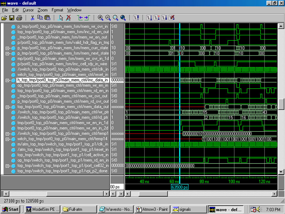
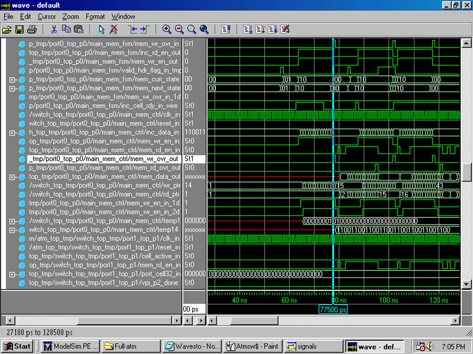
The above FSM explains the operations inside the MMF
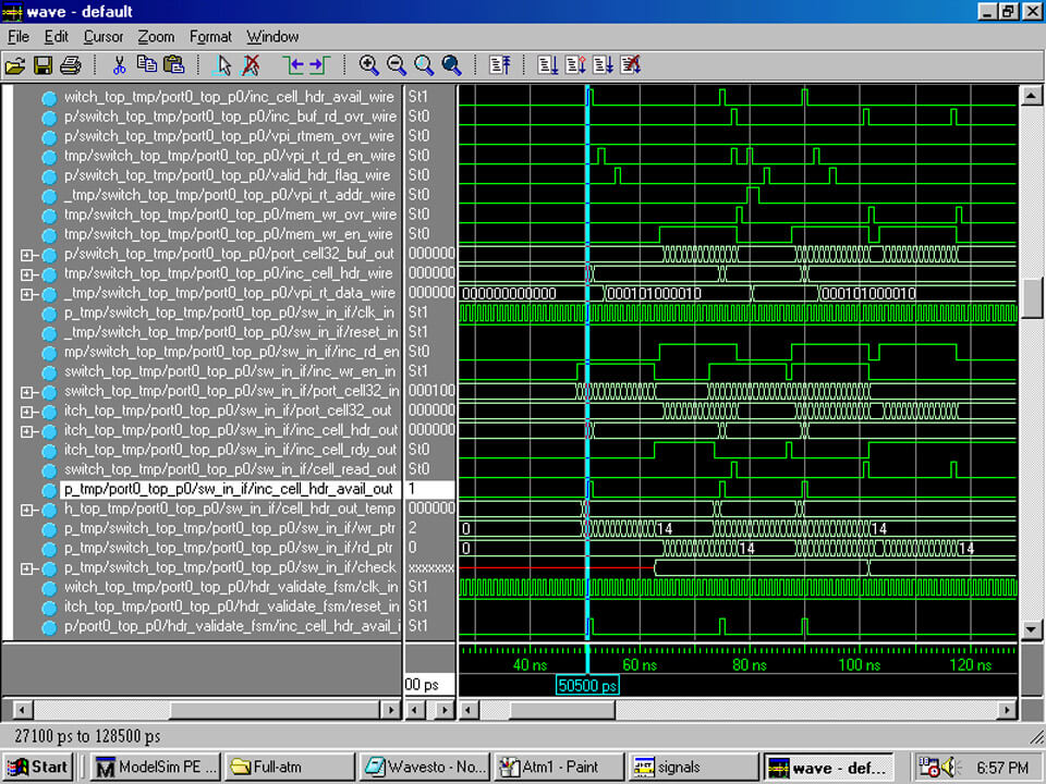
When the valid-hdr-flag-in is set, transfer from the idle state to the val-hdr state takes place. When inc-cell-rdy-in is set transfer to gen-en state takes place. In gen-en state, the MMF sets the mem-wr-en-in is set for MMC and inc-rd-en-in is set for the SII.
On receiving the inc-rd-en-in, the SII writes the cell into internal buffer of MMC via port-cell32-out.When the cell has been written into MMC, mem-wr-ovr-in flag is set and transfer to idle state takes place.
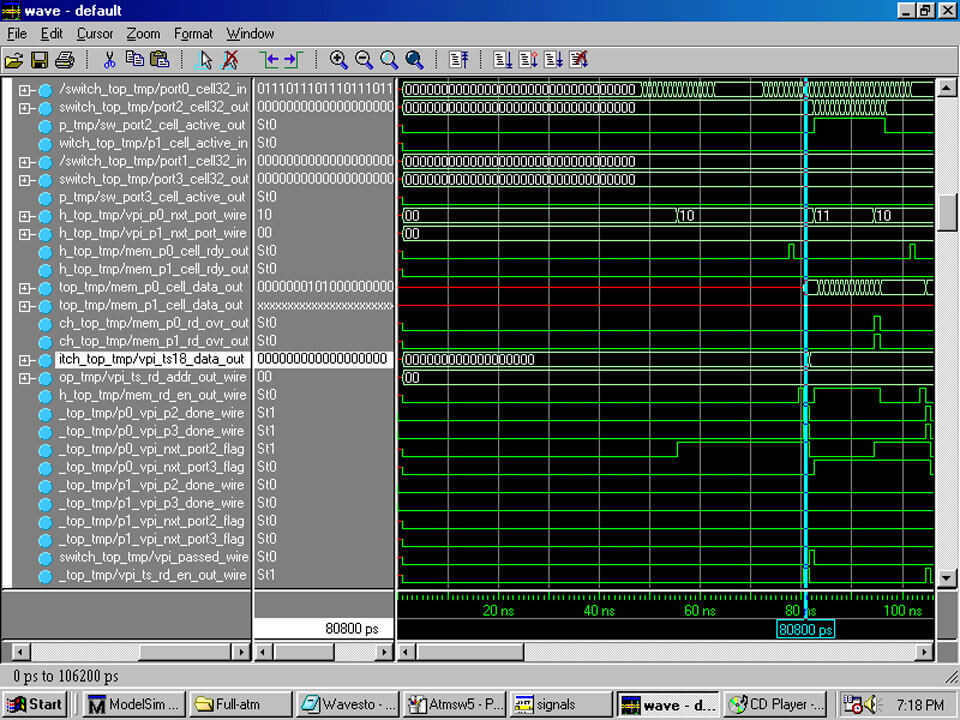
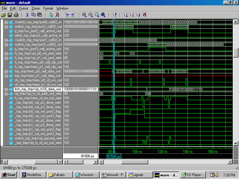
The above FSM explains the operations inside the MSF.
When mem-cell-rdy-in flag is set by MMC, transfer from idle state to gen-hdr-rd state takes place. In this state mem-rd-en-in flag is set for MMC, and transfer to gen-ts-rd state takes place. Here, vpi-ts-rd-en-in flag is set for VTT, and address is sent through vpi-ts-rd-addr-in line, and transfer to comp-vpi state takes place. Here the VPI’s are compared ,and if found to match, transfer takes place to append-vpi state. In this state, cell header VPI is translated, and first 4 bytes is sent to reassembly module via cell-32-out line. If not, the next address is sent and the process is repeated. If no match is found even when the process has been repeated for all addresses, it transfers to drop-cell state where the cell is discarded. After sending the first 4 bytes it transfers from append-vpi state to send-cell state where the remaining bytes are sent through cell32-out line to reassembly module. Once the mem-cell-rd-ovr-in flag is set by the MMC, transfer to idle state.
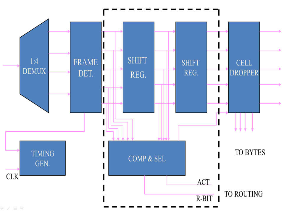
Reassembly Module
Here the ATM cells coming from main switch FSM on port-cell32-out line is received and the header is discarded. And the Start Of Packet(SOP) is attached. All cells are stored in this format with their respective SOP’s(cells of the same packet have same SOP). When an external signal is generated by the end user the cells are combined into packets using SOP as identifier.


