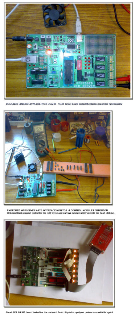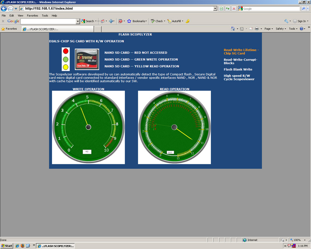

Unlike other normal flash mem-tools , the scopelyzer designed exclusive for the flash diagnostic and lifetime calculation handling. This will have tremendous usage demand in the wireless firmware download and upgrade and in all flash usage utilities , can be deployed for all ALU product series when the flash diagnostic requirement arises … The below screenshots are self explanatory,The scopelyzer sw developed by us can automatically detect the type of Compact flash connected , Secure Digital card micro digital card connected to standard interfaces / proprietary interfaces NAND , NOR , NAND & NOR with cache type will be identified automatically by our SW. Further developments are on the way to make its code footprint as small as possible and improvise its real-time characteristics based on successive experiments that were carried on the development boards and the test environment used mentioned in the below figure.
Red circular ikon here shows that the NAND CF is not accessed for any R/W operations , Green ikon blink indicates write operation in progress and the yellow ikon blink for the read operation. Write dial is calibrated from 0 to 10 , factory shipped flash chip set / cards when tested for their initial write counts will show the exact point and the software developed will automatically take that as the reference point , also this can be used as a check for the value mentioned in the data sheet matches or not vendor shipped lifetime – write count hit , the digital readout gives out the write count rates
When the read-count needle hits 12 to 13 denotes the mentioned read count has been hit and the flash card/chip set is safely recommended to operate in read only mode , this intimation is done through the warning followed by OK responses . The needle will come to a halt after completing the first round of read hits ,after which the inner semicircle takes the lead towards pointing out the number of successive reads and the digital count will increment . The inner semicircle graduations has to slowly increment from yellow to red shows the read only rate counts FT indicates the factory test read hits .
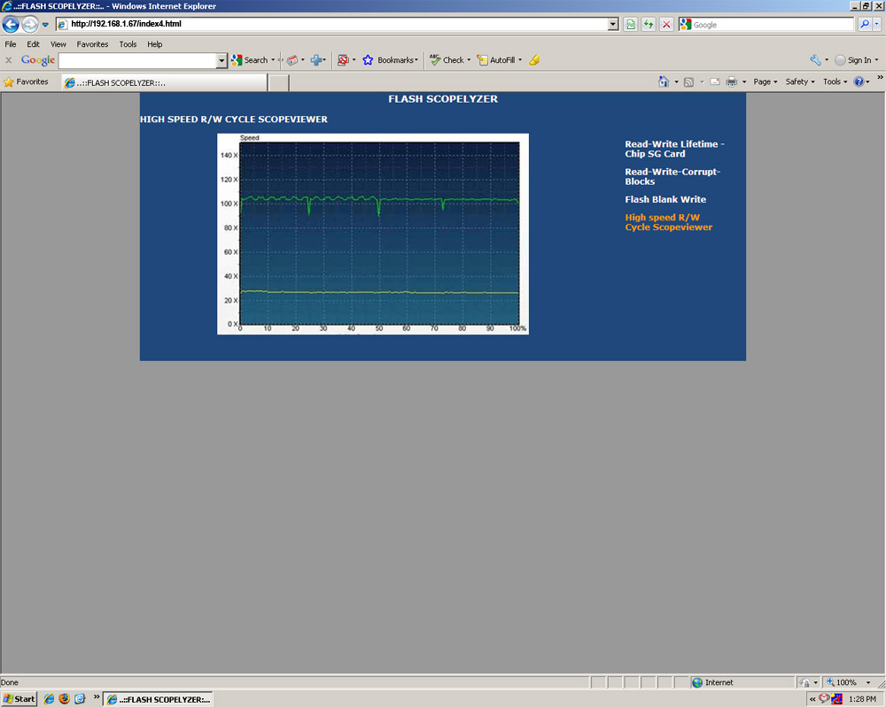
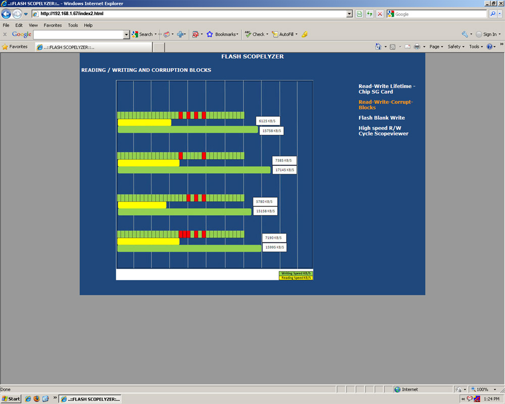
Prober driver module incorporated in the normal flash driver detects, displays in real-time the read and write speeds . Red blocks in the horizontal historiography bar signifies the corrupted sectors encountered during the write interval , bad block management scheme detects blocks that cannot be written to and reserves replacement blocks on the flash device. It extends the life of a flash card/chip set . atomic write checks in software enables strict management of the data blocks to be handled. Wear-leveling algorithms ensures the sectors/blocks are used evenly across the entire flash device.
Solid state flash chipset total life = (Endurance * Capacity)/(Write Speed*D/C*Write % * Write Amp)
Flash memory sustains a limited number of P/E (program-erase) cycles during their life and for SLC(single level cell) flash memory today it is ~100K. Calculating its life is based on a formula that uses the total number of cells available for writing and dividing by the number of bytes that can be written in a period of time.That can be translated into years, months or even days depending upon how much data is transferred. Using a standard flash chipset/card the MLC(multi level cell) memory that only supports 10K P/E(program-erase)cycles. All fields mentioned in the formulae will get updated atomically through the program-erase and after the write amplification value check .Flash management software is designed to handle the loss of data – The memory management software can implement a graceful strategy such as placing the entire flash unit in a read-only state, thereby avoiding data loss when the number of block errors exceeds a predefined number . An alarm will be raised when the user tries to write into flash at that state . Improve effective performance, maximize media lifespan. The decision between NAND and NOR memory will ultimately depend on both technical and pricing requirements of the device being built. Whatever type or combination of flash is used, it is prudent to include memory management software to prevent data loss while improving the performance and maximizing the lifespan of the memory.
Automatic flash recognition and troubleshooting this feature is a first-of-its-kind, intelligent technology that automatically detects equipment attached to the CR RFID reader. This makes the task easier by automatically displaying the name of connected flash chipsets and by providing alerts when a device goes away for any reason, a valuable feature for remote flash troubleshooting + flash page and bank level sector wise troubleshooting.
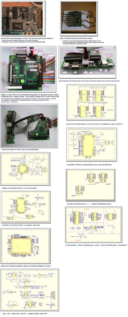
This feature is also used for the SDR wireless firmware upgrade and CR wireless upgrade, Also a new utility called called wireless JTAG download and upgrade is also showcased here associated work is in progress and the partial completion of the module test result has been shown. To test the functionality of the scopelyzer the ASTB and the target boards mentioned in detail in the below figure.