TECHNICAL SPECIFICATION OF HERO HONDA-CD 100 ENGINE
SINGLE CYLINDER FOUR STROKE WITH OVER-HEAD VALVE, AIR-COOLED
| Displacement | : | 97.2 cc |
| Bore | : | 50 mm |
| Stroke | : | 49.5mm |
| Stroke | : | 8.8:1 |
| Compression pressure | : | 13.5 ± 1.5 Kg/cm² @1000 rpm. |
| Inlet valve stem diameter | : | 5.46 mm |
| Inlet valve face diameter | : | 23.48 mm |
| Inlet valve length | : | 65.14 mm |
| Exhaust valve stem diameter | : | 5.46 mm |
| Exhaust valve face diameter | : | 20.03 mm |
| Exhaust valve length | : | 65.02 mm |
| Valve clearance | : | 0.05 mm (inlet & exhaust) in cold condition |
| Valve lift | : | 3.00 mm. |
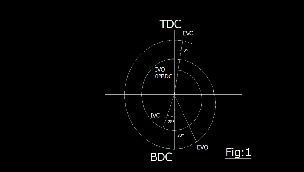
| Valve timing | : | IVO―0˚ BTDC IVC―28˚ ABDC EVO―30˚ BBDC EVC―2˚ ATDC |
| Ignition system | : | Electronic (CDI) Ignition starts―21˚ BTDC @ 1400 rpm 34.5˚ BTDC @ 4000 |
| rpm Max. horse power | : | 7.0 BHP @ 8000 rpm |
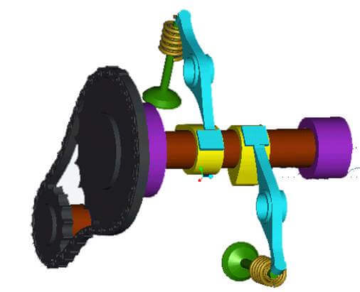
DRAWBACKS OF CAM OPERATED VALVE TRAIN MECHANISM
- The increased number of contacting surface joints in the system tends to cause more wear and tear and also more noise and vibration.
- During opening and closing of the valve, contact between the valve and rocker will impart a degree of side thrust to the valve stem and guide.
- Larger tappet clearances are necessary to compensate for the very long valve train mechanism expanding and contracting in service.
- Motion from the cam to the valve is basically trying to bend the rocker-arm in case of overhead camshaft mechanism with pivoted rocker-arm.
- A much more elaborate drive from the crank-shaft to the camshaft is necessary, like driving-sprocket, chain or gear-train etc.
- These configurations tend to have very sensitive lubrication requirements.
- Valve clearance adjustments requires at regular interval due to wear and tear of the cam, push-road and expansion of the drive train etc.
WORKING OF CAMLESS ENGINE
The working principle of camless engine differs from conventional cam operated engine. As the name indicates, there is no camshaft in the engine. In contrast to the majority of conventional automotive engines that operate with a valve motion fixed to the crankshaft rotation through the mechanical link of the camshaft, the camless valve train system allows fully controlled valve events. Although the conventional system has proven to be convenient and safe, it’s fixed valve timing is necessary a compromise of combustion stability, fuel economy and maximum torque objectives. The camless valve train, on the other hand, allows the optimization of the intake and exhaust valve timing, motion. The intake and exhaust valve actuation based on electronically controlled solenoid which is activated by the pulse input given by the microcontroller.
COMPLETE SYSTEM OVER VIEW
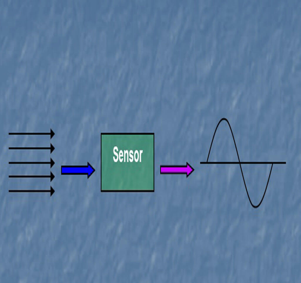
In our engine we are using two hall effect sensors, which are fitted on the flywheel to measure the flywheel angle according to the valve timing. One is foe inlet valve and other for exhaust valve. The sensor generates a voltage signal in response to the microcontroller for processing.Sensor generate a small voltage signal that varies as operating conditions change
This voltage output is the microcontroller for processing.
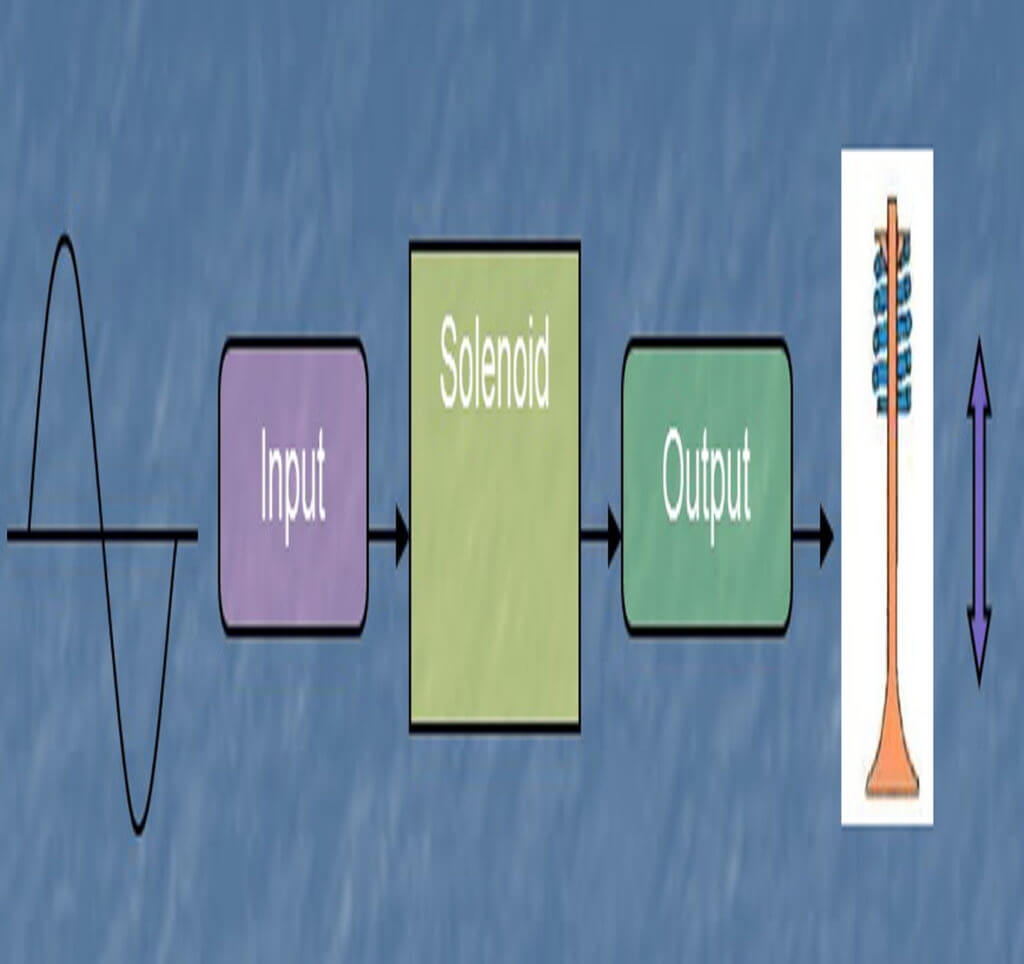
The signals coming from the microcontrollers very weak to operate the solenoid. To operate the inlet valve we need about 72 volt pulse to the intake solenoid and to operate the exhaust valve we need 224 volt pulse for few milliseconds. This problem is normally solved by integrating the battery supply with a power transistor or DC-Dc converter which is activated by the small output current signal. This circuitry is generally referred to as the output amplifier.
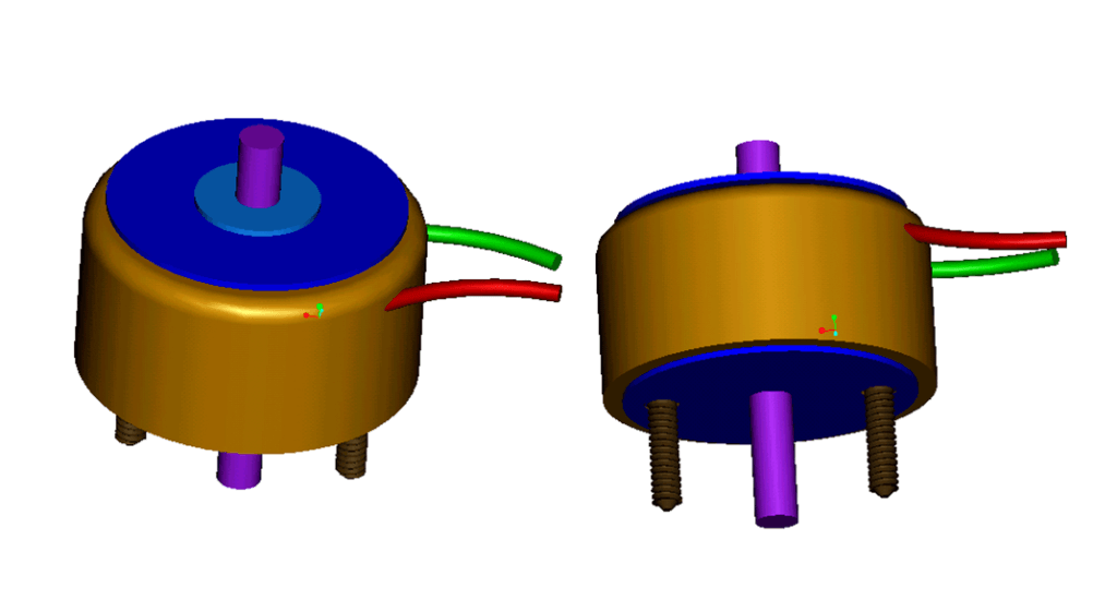
The solenoids convert the output signal sent by the microcontroller into physical movements i.e. to open and close the intake and exhaust valve.
To open the inlet valve we need 90 N force (with factor of safety) on the solenoid, for that 72 volt pulse is needed for 2 milliseconds. The greater amount of volt pulse is given by the output amplifier which is fitted in the microcontroller.
In case of exhaust valve we need 330 N force (with factor of safety) on the solenoid, and that can be achieved by ganging two solenoid on the exhaust valve. For that we need 224 volt pulse for 3.50 milliseconds. If we will supply the voltage for long time then it will cause overheat of the solenoid and solenoid may get damage.
The exhaust solenoid needs heat sink to operate in safe condition or for cooling. We are using air cooled type heat sink.
MERITS OF CAMLESS ENGINE
- Lesser number of moving parts required to operate the valves.
- Elimination of camshaft, rocker-arm, sprocket, push-rod and tappet etc. provides flexibility of this system.
- Low maintenance cost due to lesser number of moving parts and nearly zero maintenance of electromechanical solenoid and control unit.
- Precise controls of solenoid leads to batter fuel economy.
- Solenoid operated valve results less vibration and noise.
- Precise electronically controlled solenoid which operates the valve reduces the pollution at a large extent.
- These configurations enhance engine performance terminology.
- Manufacturing of camless engine is cost effective when it will go for mass production.
- Less maintenance cost, reliability of the system and its component, more volumetric efficiency, better fuel economy and in turns increased power enhance the over all performance of the engine.
- Variable valve timing can be achieved by the use of gang solenoid and aid of simple program modification.
Response time is 3.5 ms and duty cycle is 2.5% (840 Watts)
For inlet solenoid we added extra 25% to the response time and 50% for exhaust solenoid.
| RPM | ms/rev | In degree | Current applied at advance in degrees to the inlet solenoid to get proper inlet valve opening & closing at correct crank angle position | Current applied at advance in degrees to the exhaust solenoid to get proper inlet valve opening & closing at correct crank angle position | ||
| Opening | Closing | Opening | Closing | |||
| 600 | 100 | 3.6 | 15.75 | 19.35 | 23.625 | 27.225 |
| 800 | 75 | 4.8 | 21 | 25.8 | 31.5 | 36.3 |
| 1000 | 60 | 6 | 26.25 | 32.25 | 39.375 | 45.375 |
| 1200 | 50 | 7.2 | 31.5 | 38.7 | 47.25 | 54.45 |
| 1400 | 42.86 | 8.4 | 36.75 | 45.15 | 55.125 | 63.525 |
| 1600 | 37.5 | 9.6 | 42 | 51.6 | 63 | 72.6 |
| 1800 | 33.34 | 10.8 | 47.25 | 58.05 | 70.875 | 81.675 |
| 2000 | 30 | 12 | 52.5 | 64.5 | 78.75 | 90.75 |
| 2200 | 27.272 | 13.2 | 57.75 | 70.95 | 86.625 | 99.825 |
| 2400 | 25 | 14.4 | 63 | 77.4 | 94.5 | 108.9 |
| 2600 | 23.076 | 15.6 | 68.25 | 83.85 | 102.375 | 117.975 |
| 2800 | 21.428 | 16,8 | 73.5 | 90.3 | 110.25 | 127.05 |
| 3000 | 20 | 18 | 78.75 | 96.75 | 118.125 | 136.125 |
| 3200 | 18.75 | 19.2 | 84 | 103.2 | 126 | 145.2 |
| 3400 | 17.64 | 20.408 | 89.285 | 109.693 | 133.9275 | 154.335 |
| 3600 | 16.67 | 21.56 | 94.325 | 115.885 | 141.4875 | 163.0475 |
| 3800 | 15.789 | 22.8 | 99.75 | 122.55 | 149.625 | 172.425 |
| 4000 | 15 | 24 | 105 | 129 | 157.5 | 181.5 |
COIL DATA
Heat sink: 190 ×190 × 3 mm aluminum
| Duty cycle | 100% Continuous |
50% or less |
25% or less |
10% or less |
5% or less |
2.5% or less |
||
| Max ‘on’ time in seconds |
∞ |
100 |
36 |
10 |
3.6 |
1.296 |
||
| Watts at 20° C |
21 |
42 |
84 |
210 |
420 |
840 |
||
| AWG no | Resistance Ω±10%(at 20° C) |
No. turns |
Volts DC |
|||||
|
21 |
1 |
228 |
4.5 |
6.4 |
8.9 |
14.1 |
19.6 |
27.2 |
|
22 |
1.68 |
301 |
5.7 |
8.1 |
11.4 |
17.9 |
25.2 |
35.5 |
|
23 |
2.7 |
384 |
7.2 |
10.1 |
14.3 |
23 |
32.5 |
46 |
|
24 |
4.3 |
486 |
9 |
12.7 |
18 |
28 |
40 |
58 |
|
25 |
6.66 |
590 |
11.5 |
16.2 |
23 |
36 |
51 |
72 |
|
26 |
10.3 |
737 |
14 |
20 |
28 |
44 |
62 |
89 |
|
27 |
15.7 |
900 |
17.7 |
25 |
35 |
56 |
78 |
109 |
|
28 |
26.6 |
1190 |
23 |
32 |
45 |
72 |
101 |
141 |
|
29 |
38 |
1380 |
28 |
40 |
56 |
89 |
125 |
175 |
|
30 |
62.1 |
1768 |
36 |
51 |
71 |
113 |
159 |
224 |
|
31 |
96.1 |
2166 |
45 |
64 |
90 |
143 |
202 |
285 |
|
32 |
157 |
2816 |
57 |
80 |
113 |
179 |
253 |
358 |
|
33 |
241 |
3432 |
71 |
101 |
143 |
226 |
320 |
453 |
|
34 |
364 |
4108 |
90 |
128 |
180 |
285 |
400 |
─ |
|
35 |
566 |
4920 |
117 |
166 |
234 |
370 |
─ |
─ |
|
36 |
910 |
6340 |
146 |
207 |
292 |
462 |
─ |
─ |
|
37 |
1224 |
6800 |
183 |
260 |
366 |
─ |
─ |
─ |
491C SOLENOID
Response time is 5.75 ms and duty cycle is 5% (420 Watts)
For inlet solenoid we added extra 25% to the response time
|
RPM |
ms/rev |
In degree |
Current applied at advance in degrees to the inlet solenoid to get proper inlet valve opening & closing at correct crank angle position |
|
|
Opening |
Closing |
|||
|
600 |
100 |
3.6 |
25.875 |
29.475 |
|
800 |
75 |
4.8 |
34.5 |
39.3 |
|
1000 |
60 |
6 |
43.125 |
49.125 |
|
1200 |
50 |
7.2 |
51.75 |
58.95 |
|
1400 |
42.86 |
8.4 |
60.375 |
68.775 |
|
1600 |
37.5 |
9.6 |
69 |
78.6 |
|
1800 |
33.34 |
10.8 |
77.625 |
88.425 |
|
2000 |
30 |
12 |
86.25 |
98.25 |
|
2200 |
27.272 |
13.2 |
94.875 |
108.075 |
|
2400 |
25 |
14.4 |
103.5 |
117.9 |
|
2600 |
23.076 |
15.6 |
112.125 |
127.725 |
|
2800 |
21.428 |
16,8 |
120.75 |
137.55 |
|
3000 |
20 |
18 |
129.375 |
147.375 |
|
3200 |
18.75 |
19.2 |
138 |
157.2 |
|
3400 |
17.64 |
20.408 |
146.68 |
167.0905 |
|
3600 |
16.67 |
21.56 |
154.96 |
176.5225 |
|
3800 |
15.789 |
22.8 |
163.875 |
186.675 |
|
4000 |
15 |
24 |
172.5 |
196.5 |
490F SOLENOID
Response time is 4.5 ms and duty cycle is 5% (420 Watts)
For exhaust solenoid we added 50% to the response time and for exhaust solenoid.
|
RPM |
ms/rev |
In degree |
Current applied at advance in degrees to the exhaust solenoid to get proper inlet valve opening & closing at correct crank angle position | |
|
Opening |
Closing |
|||
|
600 |
100 |
3.6 |
30.375 |
33.975 |
|
800 |
75 |
4.8 |
40.5 |
45.3 |
|
1000 |
60 |
6 |
50.625 |
56.625 |
|
1200 |
50 |
7.2 |
60.75 |
67.95 |
|
1400 |
42.86 |
8.4 |
70.875 |
79.275 |
|
1600 |
37.5 |
9.6 |
81 |
90.6 |
|
1800 |
33.34 |
10.8 |
91.125 |
101.95 |
|
2000 |
30 |
12 |
101.25 |
113.25 |
|
2200 |
27.272 |
13.2 |
111.375 |
124.575 |
|
2400 |
25 |
14.4 |
121.5 |
135.91 |
|
2600 |
23.076 |
15.6 |
131.625 |
147.225 |
|
2800 |
21.428 |
16,8 |
141.75 |
158.55 |
|
3000 |
20 |
18 |
151.875 |
169.875 |
|
3200 |
18.75 |
19.2 |
162 |
181.2 |
|
3400 |
17.64 |
20.408 |
172.1925 |
192.6 |
|
3600 |
16.67 |
21.56 |
181.9125 |
203.4725 |
|
3800 |
15.789 |
22.8 |
192.375 |
215.175 |
|
4000 |
15 |
24 |
202.5 |
226.5 |
2nd revolution: Exhaust valve open & close (total opening duration is 212°)
One revolution is 360°. So one complete cycle is (360° × 2) = 720°
|
RPM |
Inlet valve total opening duration in ms |
Inlet valve opening current duration in ms |
Inlet valve holding current duration in ms |
Exhaust valve total opening duration in ms |
Exhaust valve opening current duration in ms |
Exhaust valve holding current duration in ms |
|
600 |
57.78 |
2 |
55.78 |
58.89 |
3 |
55.89 |
|
800 |
43.34 |
2 |
41.34 |
44.16 |
3 |
41.16 |
|
1000 |
34.67 |
2 |
34.67 |
35.34 |
3 |
32.34 |
|
1200 |
28.89 |
2 |
26.89 |
29.45 |
3 |
26.45 |
|
1400 |
24.76 |
2 |
22.76 |
25.24 |
3 |
22.24 |
|
1500 |
23.12 |
2 |
21.12 |
23.56 |
3 |
21.56 |
|
1600 |
21.67 |
2 |
19.67 |
22.1 |
3 |
19.1 |
|
1800 |
19.26 |
2 |
17.26 |
19.63 |
3 |
16.63 |
|
2000 |
17.34 |
2 |
15.34 |
17.67 |
3 |
14.67 |